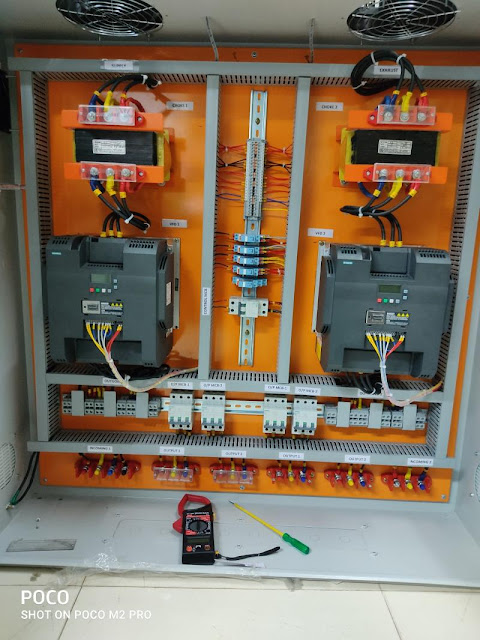
SIEMENS V20 VFD DRIVE MAIN PARAMETERS LIST
SIEMENS V20 VFD DRIVE MAIN PARAMETERS LIST

- This Parameter Setting is Suitable for ( Manual ON/OFF Mode , Auto Frequency Mode , Pot meter Varying Mode ) its Deepened on (0-10)v Dc signal.
SIEMENS V20
VFD DRIVE MAIN PARAMETERS LIST
Parameter
Setting
Description
P0003
1
Standard: Allows access into most
frequently used parameters
P0010
30
Factory setting
P0970
1
Resets all parameters
P0010
1
Quick commissioning
P0100
0
Europe [kW], motor base frequency is
50 Hz
P0301
22
Rated motor KW [KW]
P0304
415
Rated motor voltage [V]
P0305
35
Rated motor current [A]
P0307
22
Rated motor power
P0308
0.82
Rated motor cosφ
P0310
50
Rated motor frequency [Hz]
P0311
1450
Rated motor speed [RPM]
P0700
2
Terminal
P1000
2
Analog setpoint
P1080
0
Minimum frequency [Hz]
P1082
50
Maximum frequency [Hz]
P1120
30
Ramp-up time [s]
P1121
30
Ramp-down time [s]
P3900
1
End quick commissioning with factory
reset
ssP0003
3
Expert: For expert use only
P0010
0
Ready
P0701
1
ON / OFF1
P0731
52.3
BI: Function of digital output 1
P0732
52.7
BI: Function of digital output 2
P0758
0%
Value y1 of analog input scaling [%]
P0760
100%
Value y2 of analog input scaling [%]
(P1210 , 1211 ) This Parameter Settings is Only Need for VFD
Drive Auto ON After Power Failure.
P1210
Restart after mains brownout, P1211
enabled
6
Restart after mains brown- /blackout
or fault, P1211 enabled
P1211
3 (or)
Number of restart attempts
5
This
Parameter Setting is Suitable for Manual ON/OFF Mode , Auto Frequency Mode ,
Potmeter Varying Mode its Deepened on (0-10)v Dc signal.
|
SIEMENS V20 VFD DRIVE MAIN PARAMETERS LIST |
||
|
Parameter |
Setting |
Description |
|
P0003 |
1 |
Standard: Allows access into most
frequently used parameters |
|
P0010 |
30 |
Factory setting |
|
P0970 |
1 |
Resets all parameters |
|
P0010 |
1 |
Quick commissioning |
|
P0100 |
0 |
Europe [kW], motor base frequency is
50 Hz |
|
P0301 |
22 |
Rated motor KW [KW] |
|
P0304 |
415 |
Rated motor voltage [V] |
|
P0305 |
35 |
Rated motor current [A] |
|
P0307 |
22 |
Rated motor power |
|
P0308 |
0.82 |
Rated motor cosφ |
|
P0310 |
50 |
Rated motor frequency [Hz] |
|
P0311 |
1450 |
Rated motor speed [RPM] |
|
P0700 |
2 |
Terminal |
|
P1000 |
2 |
Analog setpoint |
|
P1080 |
0 |
Minimum frequency [Hz] |
|
P1082 |
50 |
Maximum frequency [Hz] |
|
P1120 |
30 |
Ramp-up time [s] |
|
P1121 |
30 |
Ramp-down time [s] |
|
P3900 |
1 |
End quick commissioning with factory
reset |
|
ssP0003 |
3 |
Expert: For expert use only |
|
P0010 |
0 |
Ready |
|
P0701 |
1 |
ON / OFF1 |
|
P0731 |
52.3 |
BI: Function of digital output 1 |
|
P0732 |
52.7 |
BI: Function of digital output 2 |
|
P0758 |
0% |
Value y1 of analog input scaling [%] |
|
P0760 |
100% |
Value y2 of analog input scaling [%] |
|
(P1210 , 1211 ) This Parameter Settings is Only Need for VFD Drive Auto ON After Power Failure. |
||
|
P1210 |
|
Restart after mains brownout, P1211
enabled |
|
|
6 |
Restart after mains brown- /blackout
or fault, P1211 enabled |
|
P1211 |
3 (or) |
Number of restart attempts |
|
|
5 |
|
|
This
Parameter Setting is Suitable for Manual ON/OFF Mode , Auto Frequency Mode ,
Potmeter Varying Mode its Deepened on (0-10)v Dc signal. |
||
Wire Port :
- 1 st Terminal Port is ( 10 V ) OUT DC
- 2 nd Terminal Port is ( AI-1 ) ANALOG INPUT
- 5 th Terminal Port is ( 0V ) COM for ANALOG I/O
- 8 th Terminal Port is (DI-1) DIGITAL INPUT-1
- 10 th Terminal Port is (DI-3) DIGITAL INPUT-3
- 12 th Terminal Port is ( DI C ) COM for DIGITAL INPUT
- 13 th Terminal Port is (+24 V ) OUT
- 14 th Terminal Port is ( 0V ) COM for DIGITAL INPUT
- 18 th Terminal Port is (DO-2 NO) DIGITAL OUTPUT
- 19 th Terminal Port is (DO-2 COM) DIGITAL OUTPUT
Wire Connection :
- Take out ( +24v OUTPUT ) from 13 th Terminal Port and give to 8 th ( DIGITAL INPUT) Terminal port for the Purpose of ON / OFF the VFD drive with External START,STOP Push Button , and also give (+24v OUTPUT) to NO Element (RESET Button) and Take RESET Button Output give to 10 th Terminal port for the Purpose of RESET the Alarm with External Push Button.
VIDEO LINKS :
- Siemens V20 Inverter Commissioning part 1 https://youtu.be/FSW5vVIeYUM
- Siemens V20 Inverter Commissioning Part 2 https://youtu.be/W40Q1ofaexI
- Inverter Commissioning Part 3-Siemens V20 https://youtu.be/pCFd4OWagfg
- Siemens V20 Inverter Parameter https://youtu.be/hnZWgpmxDCQ


Thanks for this information
ReplyDeleteUseful
ReplyDeletegood share
ReplyDeleteI search lot of article I can't get this parameters, finally I got it thanks for sharing...
ReplyDeleteUseful information
ReplyDelete