Humidification Plant Operation Methods Part 1
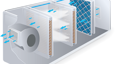
Air Washer
Pump , Ducts and
Trenches , Plant Location , Exhaust Air
System ,
Fresh Air System
Fresh Air System
Air Washer Pump
- Automatic Pump operation ON/OFF.
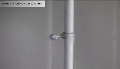
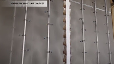
- Spray water pressure should be 2 to 3 kg/cm 2.
- Use softened water.
- Air washer efficiency should be maintained at 95%.
 |
| Automatic Water Control |
- Corrosion of machine may take place with water having high and chloride contents.
- Deposition of fine dust on machines may take place with water having mineral (salt) contents.
- Corrosion of Humidification and Air Conditioning equipment's could take place with Low pH values.
- Scale formation of Humidification equipment's occurs with high contents of Calcium and Magnesium in water.
- Air washer efficiency deteriorates with high contents of certain minerals and chlorides in the water due to poor evaporation of spray water.
Air Water Efficiency formula:
n = DBb
– Dba
➖➖➖➖ x 100
DBb – WBb
DBb = Dry Bulb Temperature of air before air washer in oC
DBa = Dry Bulb Temperature of air after air washer in oC
WBb = Wet Bulb Temperature of air before air washer in oC
n = Air washer efficiency of spray chamber in %
Parameters
- pH - 7.5 to 8.5
- Chlorides - 50 mg/l
- Sulphates - 50 to 100 mg/l
- Silicates - 10 mg/l
- Phosphates - 5 mg/l
- Nitrates - 30 mg/l
- Calcium Oxide - 120 mg/l
- Calcium Carbonate - 290 mg/l
- Magnesium - 40 mg/l
- Sodium - 25 mg/l
- Iron - 0.05 mg/l
- Presently, Mill is using Raw water with average quality of 750 TDS.
- Due to rapid evaporation taking place in the air washer section, water TDS goes upto 2000 PPM with in 10 days.
- Heavy salt content in the water will deposit scale over the Eliminators, Nozzles and Wall also.
- It is not Recommended to use more TDS (above 1200 PPM ).
- It Suggested to use softened water or RO water to reduce Scale formation in the Plant room and Improve plant efficiency.
Note :Above 90% means = GoodBetween 80 - 85 % = AverageBelow 80 % = Poor (to be improved)
Plant Location
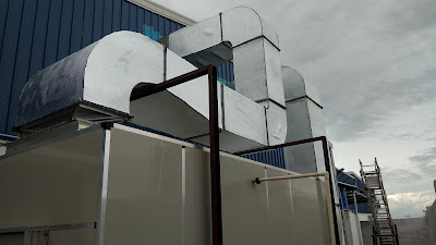
- Supply & Exhaust Plants should be nearer to the Department.
- Supply Air Plant at first floor.
- Exhaust Fan in ground floor.
- Separate pneumafil Exhaust Trench for Spinning Frames.
Ducts and Trenches
- Straight and Less Right angle bends.
- Not more then 120m length.
- Sufficient size.
- Proper Taper (1:100) ( Next Article we will discuss about Ducts and Trenches Briefly)
Exhaust Air System
- Rotary Air filter will consume more power due to more Resistance.
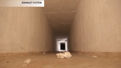
- Exhaust Trenches should be of proper in size.
- Location of the Exhaust trenches at correct place.
- Trenches are to be cleaned every week.
- Exhaust grille size and number of grilles Use Required Capacity of the Plant.
- The Exhaust Plant Room Size.
- Automatic Fan Closing sheets.
- V-Shape/Rotary Exhaust Air Filter.
- Avoid exhaust hot air leakage through the Recirculation air damper.
- Actual supply and exhaust plant capacity is to be measured by using Anemometer. ( Next Article we will discuss about Air Flow Measurement Briefly)
HEAT-LOAD
- Required humidification plant capacity is to be calculated based on the heat load of the department. ( Next Article we will discuss about Heat Load Briefly)
OPTIMISATION
- Plant capacity can be optimized by reducing the fan blade angle or by switching off the fan in multiple fan system or using inverter drives.
- Be of Higher Efficiency.
- Have Lesser Tip Clearance.
- Be Direct Driven.
- Be with Adjustable Blades.
- Be with Automatic Fan Closing Sheets.
- Hub Ratio Should be above 30%.
P = Power (kw) varies in cube of the speed.
Q = Volume (cfm) varies as the fan speed.
P = Pressure vary as the square of the speed.
Calculation of Fan Power:
Fan Power (HP) = p x 5.2 x Q
-------------
33000
p - velocity pressure in inches of wc
q - volume of air in cu.ft / min
5.2 - constant to convert inches of wc to lbf / sq.ft
SUPPLY AIR SYSTEM
- Fresh Air filters are to be cleaned every 4 hours (based on requirement)
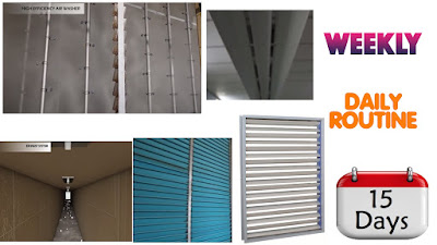
- Damper are to be cleaned and lubricated once in 15 days.
- Motors and pumps are to be cleaned daily.
- Air distribution sheets every week.
- Water spraying nozzles once in week.
- Eliminator sheets once in 3 months.
- Supply Air duct once in 15 days
- Supply Air diffusers daily.
- Exhaust air filter based on requirement (Min once in 4 hrs).
- Dampers cleaning and lubrication once in 15 days.
- Motors daily
- Exhaust air trenches weekly.
HIGHLIGHTS
SUPPLY AIR SYSTEM HIGHLIGHTS
- ATTIC ventilation will reduce transmitted heat through roof.
- False ceiling is to be insulated.
- V-shape fresh air filter.
- Sufficient size of fresh air damper will improve plant efficiency.
- Automatic fan closing sheets.
- PVC baffle type air distribution sheets.
- PVC clamp-on type water nozzles.
- ‘S’ (2 pass) Type PVC eliminator sheets.
- The correct size of the air washer section.
- The size of the supply air duct.
- Uniform air distribution system.
- Power saving of about 25% to 60% in existing humidification plants.










Very Useful Information
ReplyDeleteVery very useful information ..thank you for sharing this post and please tell heat load calculation for humidification plant
ReplyDeleteGood explanation
ReplyDeleteNice topics
ReplyDeleteTemperature control केसे kre h plant pr
ReplyDeleteRh. 85 temp. 28 केसे rkhe sr. Loom प्लांट pr
ReplyDeleteNice post...Paint Booth Manufacturers in Chennai
ReplyDeleteIndustrial Oven Manufacturers
Air Washer System
Very Informative. Thanks.
ReplyDelete