PLC Ladder Logic Instructions
Siemens PLC Programming This chapter covers the following topics (AND, OR, and Exclusive OR (XOR) Instructions , Inversion , Instructions that Set and Reset Bits , Additional Ladder Diagram Instructions )
AND, OR, and Exclusive OR (XOR) Instructions
- LAD programs incorporate configurations of instructions that represent logical conditions derived from the Boolean logic used to design computer circuits.
- Some of the most common Boolean logic functions are the AND, OR, and Exclusive OR (XOR) functions.
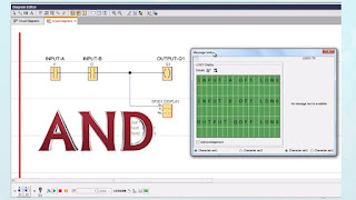
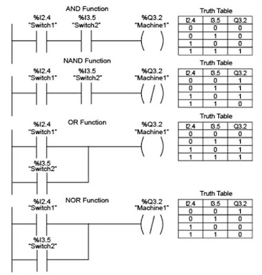
- For example the network in the graphic is an AND function.
- For this network as the associated truth table shows the only condition that causes the output coil to turn on and the Q3.2 status bit to be set to 1 is when the I2.4 and I3.5 status bits are both 1.
- In other words when the status bits for both normally open contact instructions are 1's both contacts will be closed and there will be power flow to the output coil instruction.
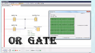
- When normally open contact instructions are placed in parallel leading to an output coil instruction an OR function is formed.
- For this network as the associated truth table shows if the status bits for either or both of the normally open contact instructions are 1 the Q3.2 status bit is set to 1.
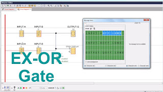
- The XOR function is formed using normally open and normally closed contact instructions leading to an output coil instruction.
- As the truth table for this function shows Q3.2 is 1 if either I2.4 or I3.5 is 1 but not if both are 1's.
Inversion
- The inverted output coil instruction is one example of inversion which means changing 1 to 0 or 0 to 1 and is sometimes called negation.
- To understand this better consider the networks shown in the graphic.
- The AND and OR functions previously described are shown along with similar logic that uses an inverted output coil instruction.
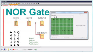
- This results in logical operations that are sometimes referred to as NAND and NOR functions.
- Notice that the truth tables for these functions show the resulting states for Q3.2 to be inverted in comparison to the truth tables for the AND and OR functions.
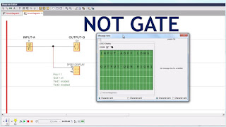
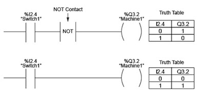
- The NOT contact instruction shown in the graphic is another example of a logic inverter.
- If there is no power flow to the NOT contact instruction there is power flow after the NOT contact instruction and vice versa.
- Note that the truth table for the network with the NOT contact instruction shows the states of output Q3.2 as inverted from the states shown for the network without the NOT contact instruction.
- Because the inversion occurs each time the network is scanned the NOT contact instruction does not have an operand.
- Although S7-200, S7-300, and S7- 400 PLC'S do not have an inverted coil output instruction adding a NOT contact instruction prior to an output coil instruction has the same effect.
Instructions that Set and Reset Bits
- There are a variety of LAD instructions for setting and resetting bits.
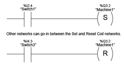
- For example the graphic shows networks with set and reset coil instructions.
- When there is power flow to the Set coil instruction the bit specified by the instruction's operand is set to 1.
- When there is power flow to the Reset coil instruction the bit specified by the instruction's operand is reset to 0.
- In this example when I2.4 is set to 1 the normally open contact closes there is power flow to the set coil instruction and Q3.2 is set to 1.
- Output Q3.2 remains a 1 even if I2.4 later goes to 0.
- When I4.3 is 1, there is power flow to the reset coil instruction and Q3.2 resets to 0.
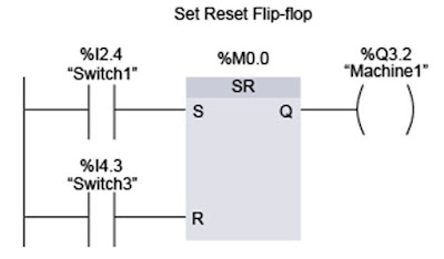
- The graphic shows a set reset flip-flop another instruction that sets and resets bits.
- When there is power flow to the set (S) input the output (Q) and the memory bit specified by the operand at the top of the instruction are both set to 1.
- They remain a 1 even if there is no power flow at the set input until there is power flow at the reset (R) input.
- For the set reset flip-flop the reset input is dominant.
- In other words with power flow at both the set and the reset inputs the output and memory operand for the set reset flip-flop are both 0.
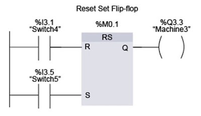
- Next consider the lower network in the graphic which includes a reset set flip-flop instruction.
- This instruction functions the same as a set reset flip-flop instruction except that the set input is dominant In other words with power flow at both the set and the reset inputs the output and memory operand for the set reset flip-flop are both 1.
- In the examples shown note that a bit memory (M) address is used as an operand.
- Using a bit memory address rather that an input (I) or output (Q) operand avoids the problem of picking an operand that could otherwise be used by the PLC'S I/O modules.
Additional Ladder Diagram Instructions
- The instructions shown in this lesson are only a few of the many types of instructions that can be included in a Siemens PLC LAD program.
- A LAD program can include a variety of basic and extended instructions.
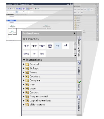
- The Basic instructions are grouped in the following categories
- Bit Logic Instructions
- Timers
- Counters
- Compare Instructions
- Math Instructions
- Move Instructions
- Convert Instructions
- Program Control Instructions
- Word Logic Instructions and
- Shift and Rotate Instructions
- The extended instructions are grouped in the following categories
- Clock and Calendar
- String and Character
- Program Control
- Communications
- Interrupts
- PID
- Motion Control and
- Pulse
- In combination the basic and extended instructions provide an extensive set of instructions that allow Siemens PLC'S to perform the full range of Automation tasks.
Next Chapter we will discuss about ( Basic Function block diagram) Topics.
SIEMENS PLC Class for Beginners




Comments
Post a Comment