PLC Ladder Programming Concepts
Siemens PLC Programming This chapter covers the following topics (Ladder diagram programming , Bit Logic Instructions , Power Flow , Contact and Coil Instructions )
Ladder Diagram Programming
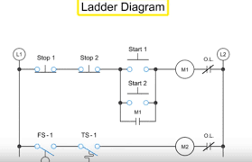
- Ladder diagram programming (LAD) also called ladder logic is a graphical programming language derived from the diagrams used for electromechanical control circuits and expanded to include more advanced capabilities.
- The graphic shows two completed LAD networks and one network yet to be programmed.
- The networks are numbered beginning with the top network (network 1).
- Because networks resemble the logic of a ladder a network is sometimes referred to a rung.
- As the CPU executes the user program it scans each network from left to right beginning with the instructions closest to the power rail which is the vertical line shown on the left in each network.
Bit Logic Instructions
- One of the ways that PLC'S use binary bits is to represent the on or off condition of inputs and outputs.
- Within an S7 PLC CPU there is a portion of memory referred to as the process image.
- The process image has a bit assigned to every possible input and output even those inputs and outputs that are not connected to devices.
- For example input 2.4 (I2.4) is associated with input bit 4 of input byte 2 in the process image.
- Input (I) and output (Q) bits in the process image along with a type of memory called bit memory (M) are collectively called global memory because these memory areas are available to all code blocks.
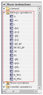
- Instructions like the ones shown in the graphic that perform logical operations using single-bit memory locations are referred to as bit logic instructions.
- Because the LAD programming language includes many instructions STEP 7 groups instructions into categories.
- As the graphic shows there are a number of basic and extended instruction categories.
- This lesson provides examples of some of the instructions in the bit logic category.
Power Flow
- Even though a network in a LAD program is an arrangement of computer instructions each network is said to control power flow from the power rail.
- In programming terminology this examination of logical conditions is called solving the logic and the solution of a configuration of instructions is called the result of logic operation (RLO).
- For example when the normally open contact instruction shown in the graphic permits power flow to the output coil instruction the RLO to the output coil instruction is a logic 1 and the output coil instruction is executed.
- When the normally open contact instruction does not permit power flow the RLO to the output coil instruction is a logic 0 and the output coil instruction is not executed.
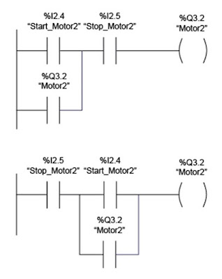
- Next consider the upper network in the graphic.
- The normally open Start_Motor2 contact instruction is in parallel with the normally open Motor2 contact instruction and power must flow through one or both of these contact instructions to get to the Stop Motor2 normally open contact instruction.
- Then the Stop_ Motor2 normally open contract instruction must permit power flow in order for the Motor2 output coil instruction to turn on.
- Although the lower network in graphic has different connections the logical solution to both networks is the same.
- Admittedly as the lower network is solved by the CPU the 'Stop_Motor2T contact instruction is examined first but that does not change the conditions under which power flows to the output coil instruction.
Contact and Coil Instructions
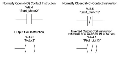
- The graphic shows four AD instructions.
- Do not confuse these instructions with electrical devices.
- These are instructions that follow simple rules.
- The normally open contact instruction is closed and will pass power flow when the status bit specified by the operand is 1.
- The normally closed contact instruction is closed and will pass power flow when the status bit specified by the operand is 0.
- The output coil instruction sets the status bit specified by the operand to 1 when the instruction receives power flow.
- The inverted output coil instruction which is not available for S7-200, ST-300, and S7-400 PLC'S sets the status bit specified by the operand to 1 when there is no power flow to the instruction.
- To understand how these rules work consider the network shown in the graphic and the truth table for this network.
- The truth table shows all the possible logical combinations associated with a network and the resulting output condition for each combination.
- Because this network includes two series contacts both contacts must be closed to pass power to the output coil instruction.
- For this to occur I2.4 must be 1 and I3.5 must be 0.
- When this condition exists Q3.2 is 1 Otherwise Q3.2 is 0.
- Next consider the truth table for the lower network in the graphic.
- The final instruction in this network is an inverted output coil instruction.
- The inverted output coil instruction gets its name from the fact that it turns on when the RLO to the instruction is 0 which is an inverted result from that of an output coil instruction.
- In this example when I2.4 is 1 and I3.5 is 0 there is power flow to the inverted output coil instruction and output Q4.1 is 0.
SIEMENS PLC Class for Beginners


Comments
Post a Comment