Siemens Modular Programming
Siemens PLC Programming This chapter covers the following topics (Modular Programming , Program Blocks , CPU Memory, Data Types).
Modular Programming
- A PLC executes its program in a cyclic manner referred to as a scan.
- A PLC program can be organized as a linear program or a modular program.
- As shown on the left in the graphic a linear program has all the instructions in one block and executes these instructions in sequence in each PLC scan.
- A linear program works well when the program is simple and does not need to vary from one PLC scan to another.
- As shown on the right in the graphic a modular program is composed of multiple program blocks.
- Some program blocks are executed in each PLC scan and other program blocks are executed under special circumstances such as during startup at specific times when a special process event occurs or when an error or interrupt occurs.
- An interrupt is a special signal or condition that causes a PLC to immediately perform a specific task In programming terminology when a program block initiates another program block the initiating block is said call the other block.
- This causes the calling program block to temporarily halt its execution until the called program bock completes its execution.
- Then the calling lock resumes its execution.
- As shown in the figure program blocks can also be nested.
- This means that one program block can call another program block which can call another program bock.
- This provides additional flexibility in programming.
- As compared to a linear program a modular program with program blocks that perform functional tasks is easier to understand, develop, and debug.
- In addition a modular program often performs better because it can vary the tasks from one PLC scan to another based on the needs of the application.
Program Blocks
- An S7 PLC program can include data blocks (DBa) and three types of program blocks
organization blocks (OB'S),
function blocks (FB'S) and
functions (FC'S) Program blocks also called code blocks are blocks that include instructions.
- The term function block does not mean the same thing as function block diagram (FBD).
- FBD is a programming language and any of the three types of program blocks can be programmed in any of the allowed programming languages.
- OB'S define the structure of the program.
- Every program must have at least one OB.
- If it has only one OB that block is identified as OB1.
- In a linear program all the code is in OB1.
- A modular program can be composed of multiple OB'S each with a unique number.
- OB1 is the main program block and it controls the execution of the user program.
- OB1 is also called a program cycle OB because it is executed each scan cycle while the CPU is in RUN mode.
- A PLC program can have additional program cycle OB'S as well as other types of OB'S that are executed conditionally such as at startup, at set time intervals, or when an interrupt occurs.
- FC'S and FB'S contain the program code that performs specific tasks.
- An FB uses an associated DB.
- An instance DB stores data for one FB.
- A global DB contains data that is available to any code block.
- An FC cannot have an instance DB and the output data values from the FC must be written to memory addresses or to a global DB.
- FC'S and FB'S are often referred to as subroutines.
- A subroutine is a portion of a program that is executed when certain conditions are met.
- A common modular program application involves one PLC controlling multiple machines or devices with the same functionality.
- For example a factory may have multiple motors that must be controlled in the same way by the same PLC.c
- As shown in the graphic this can easily be done using one FB that is called multiple times per PLC scan using a different instance DB for each.
CPU Memory
- S7 CPU'S have the following memory areas: [ load memory, work memory, retentive memory, local memory, and global memory ].
- The amount of each memory type available varies with the CPU model.
- Load memory stores all code blocks, data blocks, technology objects, and hardware configuration.
- Load memory is retentive memory which means that it's contents are retained in the event of a power loss.
- Load memory for an S7-1500 CPU is stored on a SIMATIC memory card.
- Load memory for an S7-1200 CPU can be stored either in the CPU or on a SIMATIC memory card.
- A SIMATIC memory card can also be used to transfer the user program and data to another CPU.
- The CPU copies some elements of the user program from load memory into work memory during program execution.
- Work memory is volatile memory which means that the contents of work memory are lost when power is lost but the CPU restores work memory contents when power is reapplied.
- Work memory in an S7-1500 CPU is divided into two areas code work memory and data work memory. Code work memory contains parts of the program code.
- Data work memory contains parts of the data blocks and technology objects.
- Retentive memory is non-volatile memory for saving a limited quantity of data.
- For example the tags and operand areas that have been defined as retentive are saved in retentive memory.
- Local memory (L) is temporary memory used during the processing of a program block.
- Global memory is memory that is accessible to any program block in the user program.
- Global memory includes bit memory (M) and image tables for inputs (I) and outputs (Q).
Assigning CPU Memory Areas to Instructions
- Most instructions in a PLC interact with one or more bits,bytes, or words in the CPU memory.
- The amount of memory used depends on the type of instruction.
- The specific memory locations used are identified by operands.
- For example the instructions shown in the graphic each use a one-bit memory location.
- The operand for the normally open contact instruction indicates that this instruction is controlled by the I2.4 status bit and the operand for the output coil instruction indicates that this instruction controls the Q3.2 status bit.
- This type of operand is called an absolute operand and is preceded by the % symbol when displayed in STEP 7 (TIA Portal).
- STEP 7 also allows use of alphanumeric tags as operands.
- Tags are useful because they aid understanding of the program.
- A tag preceded by # is assigned to one program block.
- A tag enclosed in quotation marks is available to any program block.
- For example a normally open contact instruction might have a tag such as 'Start_Motor2 T to indicate that it is being controlled by the start push button for motor 2 or an output coil instruction might have a tag such as "Motor2* to indicate that it is controlling motor 2.
- As shown in the figure one way a tag can be created is by assigning it to an instruction in the user program and then dragging the tag to the associated input or output in the device view.
- As tags are created program they are also added to the PLC tag table.
- Another way to create a tag is by entering it into the PLC tag table directly and then dragging the tag to an input or output in the device view With either approach the PLC tag table is a useful tool for keeping track of tags.
Data Types
- To determine how an instruction in a PLC program interprets bits in the locations designated by the instructions operands you must know the data type the instruction assigns to these bits.
- There are many data types and they are often represented by shorthand names such as DWord or Sint.
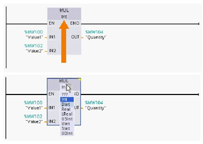
- For example the graphic shows a multiply instruction with a signed integer (Int) data type.
- As shown in the lower part of this graphic the instructions data type can be easily changed.
- When making this selection make sure that the data type is compatible with the instructions operands.
- PLC data types of various lengths are specified for binary numbers, integers, floating point numbers, date and time, characters, parameters, system data, and other types of data.
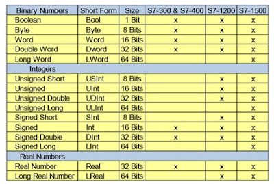
- Because the number of data types has increased over time not all data types are available for all Siemens PLC'S.
- The table shows the binary number integer, and real number data types available for some modular Siemens PLC'S.
- Additional information on these and other data types is available in the documentation for each PLC model.
SIEMENS PLC Class for Beginners


Comments
Post a Comment