Heat Load Calculation Method for Humidification Plant
In This Article we are going to see Heat Load Calculation Method and Heat Load Analysis for Humidification Plant..
Heat Load
In order to determine the humidification power required for any department, the heat load of the department is to be found out.
The heat load of the department can be broadly classified as
1. Internally generated heat load
2. Transmitted heat load
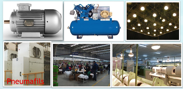
The internally generated heat load is due to the heat liberated by the following ways :
- Driving motors
- Machinery's
- Compressors
- Pneumafils
- Overheat Cleaners
- Lighting Load
- Heating Lamps
- Persons working inside the Department
- The Transmitted heat load is the heat that comes from Outside- through the roof, walls, windows and doors as the outside Temperature is higher (Most of the period) than the inside department Temperature.
- The Parameters for the heat load analysis are given in the following Tables.
- The Heat load and the power required for the supply,exhaust and pumping system.
The Transmitted heat load has been calculated for the department taking into account :
- The department size
- The roof arrangement
- Provision of false ceiling
- Thickness of walls
- size of the doors and windows
The outside maximum Temperature prevailing during peak summer days.
Parameters
- Installed Motor KW
- Lighting Load in KW
- Number of Persons (day)
- Department Size (m)
- False Ceiling
- False Ceiling Height (m)
- False Ceiling Insulation
- False Ceiling Thickness (mm)
- Roof Type
- Roof Material
- Total Heat Load (k.cal./hr)
- Supply Air Capacity Required (m 3/hr)
- Supply Air Capacity Existing (m 3/hr)
- Supply Air Capacity Existing (m 3/hr) inclu.WRS
Heat Load Analysis
- In This section, the pattern of heat in the various department of the mill has been analysed taking into account the heat generating sources inside the department and the transmitted heat that comes from outside through roof, walls, windows and doors.
- Based on the heat load analysis, the power required for the humidification system namely supply, pumping and exhaust are derived and compared with the existing humidification power.
Plant Motor Loading Analysis
- In this section the loading based on actual power consumed by the supply air fan motors, Exhaust air fan motors and pump motors have been analysed.
Temperature and RH Pattern Analysis
- In this section pattern of Temperature and RH existing in the ring spinning departments of the mill has been analysed.
Recommendation for Immediate Implementation
- In this section various suggestions are given for immediate implementation to improve the operational efficiency of the existing humidification system.
Humidification Plant Details
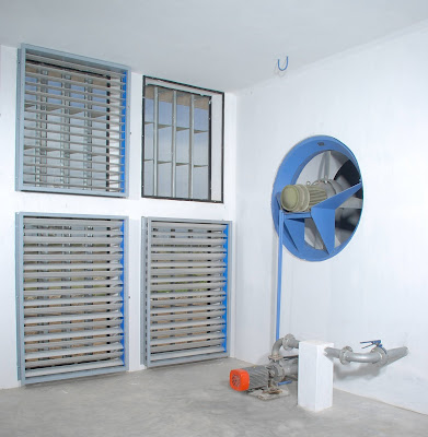
- The details of all the humidification plant namely, the HP of the fan motors, the speed and diameter of the fans and the HP of the pumps for e.g
Supply Air System
Plant : Spinning
Fan Range : 11 KW
Fan Dia (mm) : 1200
Fan Blade : Adjustable
Fan Speed (RPM) : 1450
Air Washer Section
Plant : Spinning
Pump Range : 5.5 KW
Total Nozzle : 240
Nozzle Type : Clamp-on
Nozzle Material : PVC
Heat Load Estimation
The Total heat load for a department is made up of two heat sources.
- Internal heat load and
- External heat load.
- Internal heat load is due to the frictional heat by machine, workers and light.
- It constitutes about 60 to 70 % of the total load in most of the departments.
- The heat due to lighting and the persons working in the department forms part of the total heat load.
External Heat load
- External heat load sources is due to transmission and Radiation of solar heat and heat content of outside air infiltrating into the department through doors and other openings.
- The heat transmission through walls, windows, and Roof varies considerably from season to season and even during a day from morning, mid-day and evening.
Basic factors for heat load estimation
- Establish latitude of the textile mill location together with data of outside conditions.
- Summer : Maximum mean dry bulb temp and relative humidity.
- winter : Minimum mean dry bulb temp and relative humidity.
- Find out the altitude, if the mill is located considerably above mean sea level.
Consider general particulars of the factory building such as :
- Type of building (Flat roof , North light)
- Material and thickness of construction of roof, false ceiling, walls and orientation of the building.
- Any other departments adjacent to the one under consideration.
- Obtain the individual motor loads (KW or HP) of the various machines.
- Consider capacity of existing humidification plans, if any.
Ducts
Classification of ducts ,The ducts are classified on the basic of either velocity or pressure of the air being conveyed.
Velocity
- Low velocity and
- High velocity systems
- Low velocity systems are used when the air velocity inside the ducts is less than 12 metres / sec (2500 Fpm).
- High velocity systems are used when air velocity inside the ducts are higher.
- Removal of heat and fluff while removing air is carried out by :
- Underground masonry trenches if the department is at ground level or Through metallic ducts attached to the ceiling of the lower floor, if the department is located on upper floors.
- The design consideration are the same as those for supply air systems.


Useful Topic
ReplyDeletevery interesting
ReplyDeletevery very useful topic
ReplyDeleteVery informative. Thanks.
ReplyDelete