TREND 3RM/24 Volt ac Three Relay Module (24 Volt ac , dc) Overview
In this Article we are going to discuss about TREND 3RM/24 Volt ac Three Relay Module (24 Volt ac , dc) Overview,
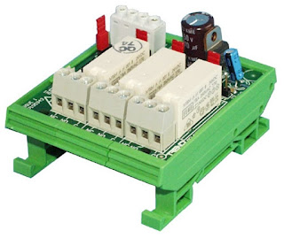 |
| TREND 3RM/24V |
Features:
- Dual function; Heat/Cool or Triple Relay, link selectable.
- AUTO ON , OFF manual override links.
- LED status indication.
- Standard DIN rail mounting.
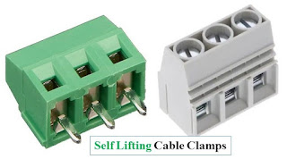
- Rising cage clamp terminals.
- 24 Volt ac , dc input power supply.
OPERATION :
- The Three Relay Module (3RM) converts an analogue output of an IQ controller to three stages of relay output, and acts as an interface between the controller and heating and ventilating equipment.
- It may be configured as a Fan , Heating ,Cooling sequence controller (Heat Cool Mode - HCM) or a 3 stage sequence controller (Triple Relay Mode - TRM), using the operating mode link.
- There are manual override links for each relay to aid commissioning.
- Field wiring is facilitated by rising cage clamp type terminals, and a supply loop terminal aids wiring to additional modules.
- In the HCM and TRM modes the relays switch in the sequences shown in the tables below.
Note:
- That the voltage levels shown in the tables are approximate values exact switching points are lower and may vary slightly from unit to unit.
- Typical threshold values are shown in brackets. The 3RM, linked for TRM and with special wiring (see below), may also be used for binary switching allowing the switching of two unequal loads (Equipment 1 and Equipment 2). When used in this way it will switch the plant as shown in the adjacent table.
FUNCTIONALITY
Mounting:
The 3RM is
designed to be mounted on a standard DIN rail.
Power connection:
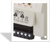
The relays power connection is made to a 24 Volt dc (e.g. IQ x auxiliary supply) or a 24 Volt ac supply (isolated or earthed, grounded, to IQ earth, ground) using the 0 Volt and 24 Volt terminals.
AUTO ON , OFF:
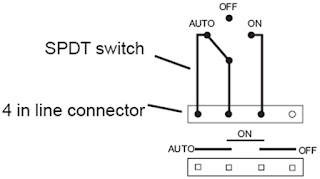
For commissioning purposes each relay may be switched ON or OFF using its AUTO ON , OFF links. The relay operation may be checked by monitoring its LED. Each AUTO ON , OFF link can be replaced with a SPDT switch.
Note :
That
feeds switched from other relays on the same module or interlocks provided by
other relays will not necessarily be operative when using manual overrides. It
is the system designer’s responsibility to ensure that adequate interlock protection
is built into the design.
Connectors:
Single part with rising cage clamp terminals for 0.5 to 2.5 mm 2 cross section area (20 to 14 AWG) cable are used for inputs, outputs, and power connection. Use copper cable only. All terminals are rising cage clamp type. Each AUTO ON , OFF link can be replaced by a 4 in line connector for connection of a switch .
DISPOSAL :
All plastic and metal parts are recyclable. The printed circuit board may be sent to any PCB recovery contractor to recover some of the components for any metals such as gold and silver.
INSTALLATION
The 3RM must be mounted within a secondary , protective enclosure, conforming to EN61010-1, close to the IQ controller.
The procedure involves:
- Mount the 3RM in position,
- Set HCM/TRM link,
- Set AUTO ON , OFF links,
- Set IQ analogue output channel for voltage,
- Wire the 3RM to the controller,
- Wire the 3RM to the HVAC equipment,
- Connect the 24 Volt input power supply,
- Check relay operation,
Ensure that external circuits are suitably protected against fault currents that would exceed the ratings for the switching circuits provided in this product.
Technical Specification
Input Power
Supply voltage : 24 Volt dc or 24 Volt ac ±20%
Input Power Supply current : 24 Volt ac :100 milliamps (34 milliamps per relay) ,
24 Volt dc : 45
milliamps (15 milliamps per relay)
Input signal : 0 to 10 Volt dc (10 milliamps maximum)
Relays:
Switching : 3 single pole changeover
Contact rating : 5 Amps at 240 Volt ac (cos>ø=0.4)
5 Amps at 30 Volt dc (Resistive)
2 Amps at 24 Volt dc (Inductive, T<=30ms).
NOTE:
- To meet safety requirements, relays being used must all be switching either low voltage or mains and not a mixture of voltages.
- If switching mains, they must all switch the same phase and polarity. Arc suppression circuit (RC) recommended for inductive loads, see TG200208.
- The U L rating applies to loads of up to 30 Volt.
- Operating modes : linkable HCM or TRM.
- Manual override : linkable AUTO ,ON ,OFF.
- LED : single LED for each relay, ON when energised.
Mechanical
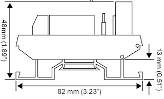
Dimensions : height 82 mm (3.23”) , width 68 mm (2.68”) , depth 48 mm (1.89”).
Environmental
Safety : EN61010-1: 2001.
U L : The USA , U L unit is rated as UL916 listed accessory to open energy management equipment.
Ambient limits
Storage : -10 °C (14 °F) to +70 °C (158 °F)
Operating : -10 °C (14 °F) to +50 °C (122 °F)
Humidity : 0 to 90 %RH non-condensing
Altitude : less than 2000m (6562 ft)
Strategy:
It is
recommended to use SET (software tool) for configuring the controller. SET is supplied
with 2RM strategy blocks for IQ1, IQ2, and IQ3 controllers. These can be used
as they are or as
examples.
There are 3 strategy blocks:
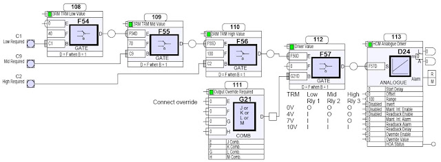
- HCM mode using analogue driver/analogue channel
- TRM mode using analogue driver/analogue channel
- HCM mode using R , L / driver , analogue channel
- These strategies are designed to apply the correct voltage to the 2RM module for the required action.
- The above is an example strategy block; this strategy drives the 3RM in HCM mode via an analogue driver and analogue channel.
We hope this Article will helpful to you , Thank you for Visit our Blog.







Comments
Post a Comment