Humidity Duct sensors Installation Methods Part 1
In This Sensor
Installation Method Article Series , Today we are going to discuss about Humidity
Duct sensors Installation Method Part-1

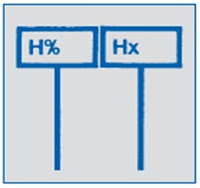
Humidity
Duct sensors
 |
| 1 |
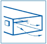
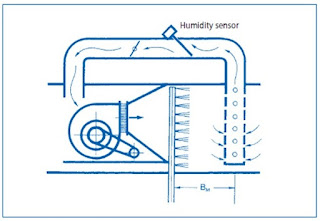
Note: That humidity sensors are affected by air velocity. The air velocity in the vicinity of the sensor must not exceed 10 m/sec.
 |
| 2 |
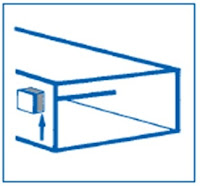
Precaution: Fit the sensor with a perforated shield or cover (e.g. perforated steel) Avoid dead-legs. (Super saturation can occur in areas where there is no air flow.)
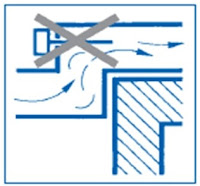
Important:
- When installing sensors in ducts with negative pressure, it is possible for air from an external source to be drawn into the device and the installation hole. (Seal tightly to prevent false readings.)
 |
| 4 |
- A test hole must be provided for every humidity sensor (downstream of the sensor). Recommended diameter: 40 mm.
 |
| 5 |
- For maintenance purposes, the electrical connections should be of the plug-in type (e.g. TT45).
 |
| 6 |
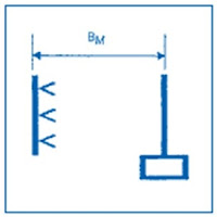
- Distance for humidification measurements for BM.
- BM is the distance between the humidifier and the humidity sensor necessary to allow the air to absorb 100% of the water supplied.
- The required distance depends on the amount of water supplied, the velocity of the air and the type of humidifier system. If the humidity sensor is not mounted at the required distance, it will produce a false reading.
Example:
Because it is in the wrong position, the sensor here measures only 30% of the water or steam introduced into the system, as only this amount has been fully absorbed in gaseous form into the air. The sensor element will get wet, produce an incorrect reading, and may be damaged.
 |
| 7 |
|
Humidification systems |
|
|
Air washers |
BM downstream of
eliminator plate |
|
Tray-type humidifier |
BM 3.5 m |
|
Spray Re-humidifiers |
BM 5.5 m |
|
Pressurized steam |
BM = Isotherm |
|
Pressure-free steam |
BM = Isotherm ・ 1.3 |
|
Spray humidifiers |
|
|
Ultrasound humidifiers |
|
|
Centrifugal humidifiers |
|
|
Atomizer humidifiers |
|
Distance for adiabatic humidification measurements
This diagram is designed for use in winter, with an absolute humidity content of 1.5 g/kg on the intake side, and a supply air temperature of 18 °C.
 |
| 8 |
Method:
- Enter the air velocity (in m/s) on the left edge of the diagram (e.g. 2.0 m/s).
- From this point, draw a line to the right, along the line indicating the increase in humidity (example: x = 10 g/kg).
- Starting where the two lines intersect, draw a vertical line and read the required distance BM for humidification measurements on the horizontal line at the bottom of the diagram (6.7 m).
 |
| 9 |
Distance BM for humidification measurements with steam
humidifiers
- A certain distance is required between humidifier and sensor, so that the air has time to absorb the water (vapour) supplied by the humidifier before the sensor measures the humidity.
 |
| 10 |
- This distance is marked on the diagram as BM.
- The minimum distance between the humidifier and the humidity sensor must be equivalent to at least BM.
Determining BM
Method:
- Enter the increase in humidity in g water/kg air (e.g. 4.5 g/kg) on the right edge of the diagram.
- Draw a horizontal line extending from this point towards the left.
 |
| 11 |
- Enter the minimum duct air velocity (in m/s) on the bottom edge of the diagram (e.g. 1.9 m/s) and draw a vertical line extending upwards from this point.
- From the point of intersection of these two lines, draw a diagonal line extending upwards and parallel to the existing diagonals. Read the distance, BM, in metres, from the scale on the edge of the diagram (example 8.5 m).
Average humidity measurement
 |
| 12 |
- Locating the humidity sensor in a bypass duct improves the measurement of average, relative or absolute humidity, and should be used:
- In cases of temperature or humidity stratification.
- Here too, the appropriate distance for humidity measurements, BM, must be maintained.
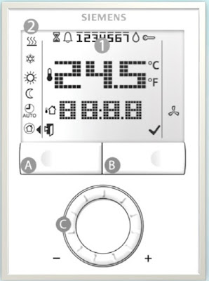
Humidity Room Sensor
 |
| 13 |
- Install sensors at a height of 1.5 m in occupied spaces, and at least 50 cm from the adjacent wall.
 |
| 14 |
- Do not install where sensor will be exposed to direct sunlight.
 |
| 15 |
- Do not install on external walls.
 |
| 16 |
- Seal gaps between cable/plastic tubing and conduit.
- Otherwise measurements will be falsified by incorrect circulation of the air.
 |
| 17 |
- Do not install near lamps or above radiators.
 |
| 18 |
- Avoid chimney walls.
 |
| 19 |
- Do not install directly adjacent to doors.

20
Well i hope this article was useful to you, thank you for visit our Blog...


Good topic
ReplyDelete