Pressure sensors Installation Method
In This Sensor Installation Method Article Series , Today we are going to discuss about Pressure sensors Installation Method , Sensor's Installation Method Series Part-2

Pressure Sensor's
Pressure
General
- Pressure sensors are affected by orientation (see manufacturer's installation instructions).
 |
| 2 |
 |
| 1 |
- Pressure tubes must be provided with an isolatable T-fitting near the device head for test purposes.
 |
| 3 |
- To prevent overload on one side when making adjustments, the connection must always be fitted with an isolating bypass.
 |
| 4 |
- Where there is a risk of condensation, the differential pressure tube must be installed at a gradient of 1:30 and fitted with a drain mechanism.
- The drainage point must be lower than the device head and sensing point.
- Protect from frost and avoid U-shapes.
 |
| 5 |
- Pressure tubes containing circulating air must not be introduced into the open air or routed through cold rooms or ducts.
- This prevents the risk of condensate freezing in the tubes (e.g. with pneumatic venting sensors).

6
- Mount on a vibration-free surface.
 |
| 7 |
- The pressure-tapping point must not be located in turbulent air.
- Ensure sufficiently long settling zones upstream and downstream of the tapping point.
- A settling-zone consists of a straight section of pipe or duct, with no obstructions.

8
Pressure
Air
- The measuring tip is screwed or glued to the duct wall.
- Seal to protect from external air.
- Remove any swarf from the inside of the duct.

9
- Protruding fixing screws will impair correct measurement.
 |
| 10 |
- Correct installation.
 |
| 11 |
- Avoid using tips which protrude into the duct for static pressure measurements.
 |
| 12 |
- Probes are used to measure static pressure in the duct.
- Must be installed parallel to the flow and either with the flow or against it.
 |
| 13 |
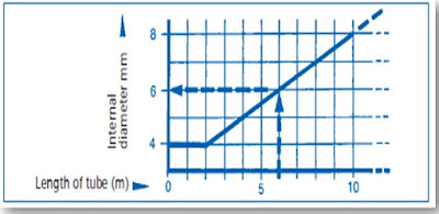
- Sizing the pressure tubes ('measuring tubes') for air and gases.
- Keep the tube as short as possible.
- An internal diameter of 4 mm is sufficient for pressure tubes of up to two meters in length.
- For longer pressure tubes, the internal diameter should be as indicated in the diagram.
- (Example: A pressure tube of 6 m requires an internal diameter of 6 mm.)
 |
| 14 |
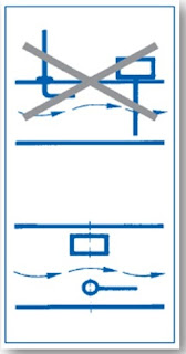
- Connect the sensor and measuring instrument to the same point.
 |
| 15 |
- The tapping point must not be located where it will be affected by obstructions to the flow.
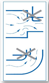 |
| 16 |
- Where more than one sensor is used, the sensors should be installed on the same plane in the flow, and not in a position where one device will obstruct the air flow to the other.
17
- dg = Equivalent diameter, Leave sufficient clearance downstream of any obstacles.

18
Pressure Room
- The end of the pressure tube leading into the room should be protected by an air permeable cover.
- Seal gaps between cable/plastic tubing and conduit.
- Otherwise measurements will be falsified by incorrect circulation of the air.

19
Options:
- Calculate average based on pressure measurements taken on several facades.
- Measure pressure in an open space (min 1.5 m above ground level).
- Multiple sensing point on flat roof.

20
Pressure
Outside air
- Measure the outdoor pressure in an area sheltered from wind. Individual facades are not suitable measurement locations, as the pressure varies according to the wind direction.
- The correct location for measurement is a place where the air can circulate freely, such as a flat roof.
Note : however, that the sensing point must be fitted with a wind
shield.

21
Pressure Liquids
Pressure tapping point:
- Sensing hole: diameter 5 mm, drilled and deburred.

22
- Smooth interior (no burrs).

23
- Use a damping coil to avoid transferring vibrations.
- Bend a 1 m long copper pipe, 4.6 mm in diameter, into a spiral with loops with a diameter of 15 cm.

24
Wrong: Air bubbles and condensate remain trapped.

25
Wrong: Condensate cannot be drained.

26
Pressure measurement in conjunction with liquids :
- Do not measure at the top of the pipe (trapped air or air bubbles) or at the bottom (dirt).
 |
| 27 |
- The correct location for a sensing point is at the side.
 |
| 28 |
- Measure at the top to prevent condensate from entering the pressure tube.
 |
| 29 |
Installation in conjunction with liquids:
- Always install the pressure sensor in a location which is lower than the sensing point.

30
Installation in conjunction with vapours/gases
- Always install the pressure sensor in a location which is higher than the sensing point.

31
Well i hope this article was useful to you, If you need more informative Article please follow our Blogger. Thank you for Visit our Blog.Have a great day.


nice topic...
ReplyDelete