Flow Velocity Air and Liquid level Sensor Installation Method
In this Article we are going to discuss about Flow Velocity Air and Liquid level Sensor Installation Method , this is Sensor's Installation Methods video series part 3
General
notes for all sensors
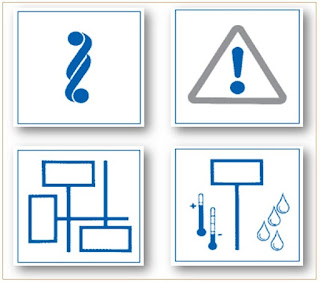
- Do not install sensors so that they protrude in any direction, and do not suspend them below the horizontal.
- Ensure that they are protected against damage and vandalism and will not cause injury.
- Be aware of the effects of orientation on the functioning of the sensor.
Always
determine the following before mounting:
- Minimum or maximum ambient Temperature
- Ambient humidity and exposure to spray water
- Exposure to vibration
- Explosion protection
- External influences
- Take account of the active and inactive sections of a sensor probe.
- A tight-sealing test-hole must be provided adjacent to every sensor.
- The cable should be installed with a drip loop to prevent water from entering the sensor housing.
- If the sensors are to be concealed (e.g. in false ceilings, shafts etc.), mark their locations visibly and record them in the site documentation.
- Always allow a sufficient length of spare cable so that the sensor can be removed at any time without disconnecting the wiring.
- When installing a sensor, avoid compressing the lagging.
- Use a graduated-diameter mounting flange to avoid compressing the lagging.
- If the mounting flange supplied does not have the appropriate graduations, use spacing bushes to avoid compressing the lagging.
- Fix a labeling plate in the direct vicinity of the sensor.
- This must include a plain text description and the reference number, which appears in the plant schematic. Do not attach the label to the device itself.
- The pressure-tapping point must not be located in turbulent air.
- Ensure sufficiently long settling-zones upstream and downstream of the tapping point.
- A settling-zone consists of a straight section of pipe or duct, with no obstructions.
Fan-belt
monitoring :
The
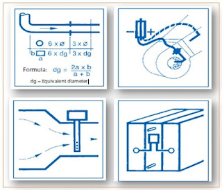
differential pressure across the fan is only suitable for fan-belt monitoring.
- Negative connection (–) on suction side use copper tube.
- Positive connection (+) on discharge side: use Pitot tube.
Flow monitoring:
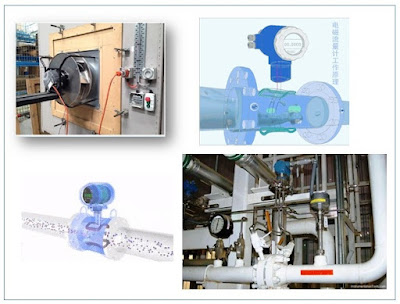
- Electro thermal flow detectors must be installed in a
zone with a high flow velocity, e.g. where pipes narrow.
- Do not monitor flow or differential pressure where flow resistance is variable, e.g. at filters, cooling coils, fans etc. Suitable locations: heating coils, silencers, baffles, attenuators.
Formula: dg =
Equivalent diameter
Flow monitoring Water :
- If differential pressure is used to monitor the flow, it is important to ensure that there are no stop valves or balancing valves between the sensing points.
Air quality Room Sensors:
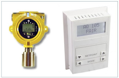
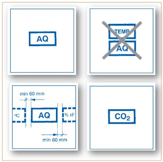
There are two types of air quality sensors:
Mixed gas or (VOC) sensors
- The accumulation of up to 24 different gases is measured in the ambient air (total concentration measured)
Selective gas sensors :
- These measure only one gas (e.g. CO2) in the ambient air (selective measurement).
- Do not locate temperature or humidity sensors above or below the AQ sensor.
- The heated sensor element produces significant intrinsic heat in the device.
- Owing to this characteristic, the room temperature or room humidity must not be measured in the immediate vicinity.
- Maintain a clearance of minimum 60 mm on each side of the AQ sensor.
- Selective gas sensors may require maintenance at regular intervals.
- Please consult the manufacturer’s instructions.
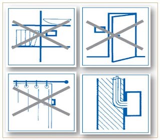
- The sensor must be installed in an accessible location.
- Avoid recesses (e.g. shelving) and alcoves.
- Do not install directly adjacent to doors.
- Do not install behind curtains.
- Seal gaps between cable/plastic tubing and conduit.
- Otherwise measurements will be falsified by incorrect circulation of the air.
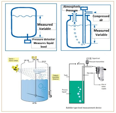
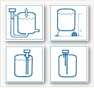
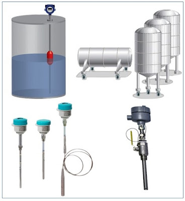
Liquid level Sensing:
A distinction is made between the following methods:
- Capacitive measuring probes
- Pressure/differential pressure (hydrostatic)
- Ultrasound
- Tank weighing systems
- Electromechanical sensing.
- The pressure is defined by the height of the liquid medium, measured from the sensor to the surface of the liquid.
- There are no critical factors to consider when installing the pressure sensor.
- The sensor material must be suitable for use with the liquid medium.
Bubble technique:
- The pressure measurement is determined by the height of the liquid above the bubble-tube outlet.
Floats:
- These are used in open and sealed systems.
- The device head must be installed above the maximum expected liquid level.
Tank weighing system :
- The measured result is determined by the tank content (mass weight).
- The sensor should be mounted in accordance with the manufacturer's instructions.
Capacitive measuring probes :
- These are used in open and sealed tanks.
Mounting:
- The distance from the next electrically
conductive component must be as specified by the manufacturer.
Conductance systems:
- These are used in open and sealed tanks.
- The measured result is determined by the length of the immersed electrodes.
Mounting:
- The distance from the next electrically conductive component must be as specified by the manufacturer.
- These are used in open and sealed tanks.
Mounting :
- The liquid-level tube and the location of the level switch are determined by the manufacturer.
- Level switches are installed at the same height as the required liquid level.
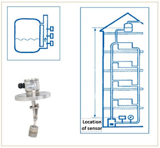
Hydrostatic level sensing:
- The measurement is based on the maximum liquid level and the location of the sensor.
Will we hope this Article is useful to you , Thank you for visiting our Blog ,
we will meet in an another good Article.








very very useful..
ReplyDeleteUseful
ReplyDelete